Series 2 FPGA Boards
ZTEX USB-FPGA Modules 2.∗ are a series of FPGA Boards with USB controller and a compatible external I/O connector. This page describes the common features and gives a summary about the FPGA Boards and accessories.
FPGA Boards - product overview
Accessories
Common Features
SDK, Examples, getting started
Description of common functions
Firmware loading
FPGA configuration
Firmware and Bitstream upload options
External I/O Connector
Pin assignment and description
Compatibility
Numbering scheme
FPGA Boards - product overview
|
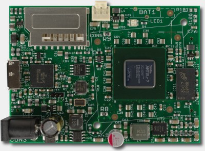
USB-FPGA Module 2.18
|
|
USB-FPGA Module 2.16
|
|
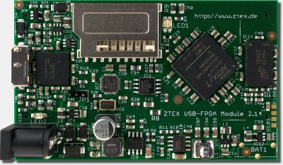
USB-FPGA Module 2.14
|
|
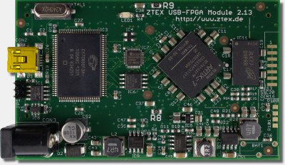
USB-FPGA Module 2.13
|
|
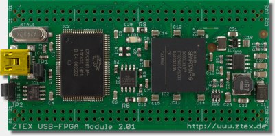
USB-FPGA Module 2.01
|
|
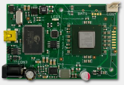
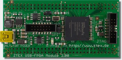
FPGA Module 2.00
|
Discontinued: |
|
|
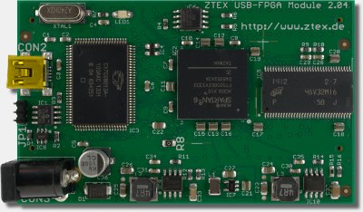
USB-FPGA Module 2.04
|
Accessories
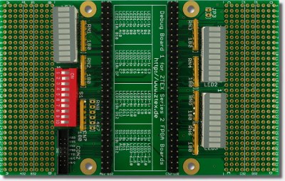 |
Debug BoardAn add-on card with many LED's, switches and a JTAG header. It is intended to simplify debugging and prototyping and is available in two variants:
|
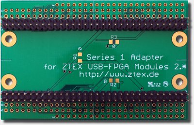 |
Series 1 AdapterAn adapter board which allows to use Series 2 FPGA Boards on application circuits for USB-FPGA Modules 1.∗. It also can be used as mounting adapter, if no application circuit is present. |
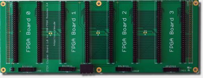 |
Cluster Base BoardConnects up to 4 FPGA Boards of the Series 2 to a small cluster node. |
|
More Accessories can be found in the ZTEX shop |
Common Features
- External I/O connector providing:
- Up to 100 General Purpose I/O's (GPIO) connected to FPGA
- JTAG signals
- Reset signal
- External power input
- 3.3V output
- I/O voltage output or input
- On-board power supply
- On-board Flash to store Bitstream
- On-board EEPROM or Flash to store Firmware
- On-board MAC-EEPROM: contains a unique non erasable MAC-address and is used to store firmware settings
- Support of SD cards as secondary Flash, see ZTEX Wiki
- SDK which covers both, the FPGA Board and the host PC
SDK, Examples, Getting Started
All ZTEX USB-FPGA Modules are supported by the ZTEX SDK. It is developed for EZ-USB FX2 and FX3 Microcontrollers and includes Firmware Kits, a host software API, utilities and many examples.A Default Firmware with flexible communication interface makes Firmware development obsolete for many applications and allows board-independent host software.
Additional documentation including Tutorials can be found on the ZTEX Wiki
In frame of the the FX3 port the SDK is currently (begin of 2016) reorganized. Development roadmap can be found on the FX3 Port page.
Description of common functions
Functions that are common for all members of the FPGA Board Series 2 are described here.Firmware loading
The EZ-USB can load firmware from two sources,- from USB and
- from non-volatile memory (FX2: EEPROM, FX3: Flash).
All Series 2 FPGA Boards have the jumper JP1 which can be used to disable firmware loading from non-volatile memory. This is especially useful if a corrupt firmware has been installed. Refer to the FPGA Board specific documentation for details.
ZTEX Series 2 FPGA Boards are delivered with a factory-installed default firmware which can be overwritten by user defined firmware using, see Firmware and Bitstream upload options
FPGA configuration
There are three ways to configure the FPGA:- Via USB using the SDK
- Via JTAG using Xilinx Tools (May be slow. Therefore the USB method should be preferred)
- From Flash using the SDK
If a Bitstream is stored in Flash the firmware automatically tries load it to the FPGA during start-up.
All Series 2 FPGA Boards have a LED which indicates the configuration state of the FPGA. Refer to the FPGA Board specific documentation for details.
Firmware and Bitstream upload options
The SDK offers several ways to upload firmware and Bitstream directly to EZ-USB and FPGA, respectively, and to non-volatile boot memory:- API:
- uploadFirmware to load Firmware directly to EZ-USB,
- nvUploadFirmware to load Firmware to non volatile boot memory
- configureFpga to load Bitstream directly to FPGA
- flashUploadBitstream to load Bitstream to Flash memory
- Command line utility FWLoader
- Server based (G)UI DeviceServer
External I/O connector
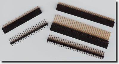
The external I/O connector is located at the bottom sid and consists in two female 2x32 pin headers with 2.54mm grid.
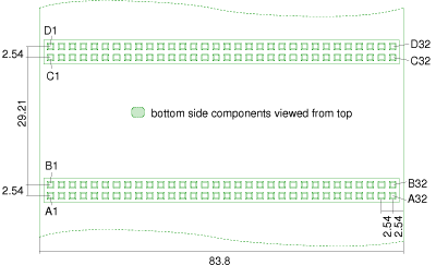
Drawing with measurements of external I/O connector of FPGA Board Series 2. (Click on the image for a PDF version.) |
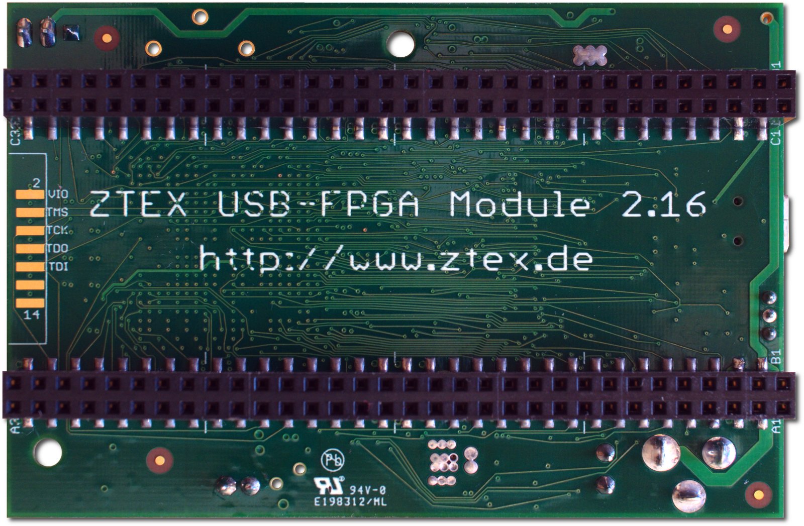
External I/O connector on bottom side of USB-FPGA Module 2.16. (Click on the image for a larger version) |
Pin assignment and description
The pin assignment and description can also be downloaded in Gnumeric or Excel format (several sheets). These tables also contains the product specific details like connection lists (net lists) and I/O voltage ranges.An Eagle library is available too.
|
|
Compatibility
Although the pin assignment described in the previous section is fixed for all Series 2 FPGA Boards, not all pins and functions are assigned in any case. In order to prevent incompatibilities at migration between FPGA Boards, some rules should be considered:- Special IO functions like differential signals and clock pins should be avoided (use internal clock sources instead)
- Not always all FPGA IO's are assigned. Currently only USB-FPGA Modules 2.04 are affected and probably future FPGA Board will be fully assigned. Nevertheless, FPGA IO's with low numbers should be avoided if possible.
- Not always IO voltage of all FPGA IO's is variable. Currently only USB-FPGA Modules 2.04 are affected and probably voltage of all FPGA IO's of future FPGA is variable. Nevertheless, if possible, IO voltage of 3.3V should be preferred.
- Pins most close to the center of the FPGA Board have best signal propagation speeds
Numbering scheme
The numbering scheme for the FPGA Boards is is 2.<n><m>, e.g. 2.16.| 2. | Series number: Is always 2. |
| <n> | FPGA Generation: |
| <m> | Board number: A larger number usually means a larger FPGA Board is some manner, e.g. larger FPGA (package), more RAM, more powerful USB controller. |